The Y-Chart In VLSI: A Complete Information To Timing Evaluation And Optimization
The Y-Chart in VLSI: A Complete Information to Timing Evaluation and Optimization
Associated Articles: The Y-Chart in VLSI: A Complete Information to Timing Evaluation and Optimization
Introduction
With enthusiasm, let’s navigate via the intriguing matter associated to The Y-Chart in VLSI: A Complete Information to Timing Evaluation and Optimization. Let’s weave fascinating data and supply recent views to the readers.
Desk of Content material
The Y-Chart in VLSI: A Complete Information to Timing Evaluation and Optimization

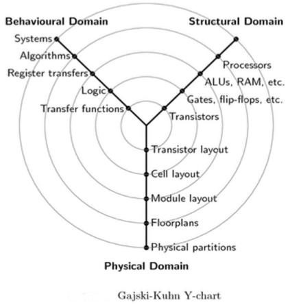
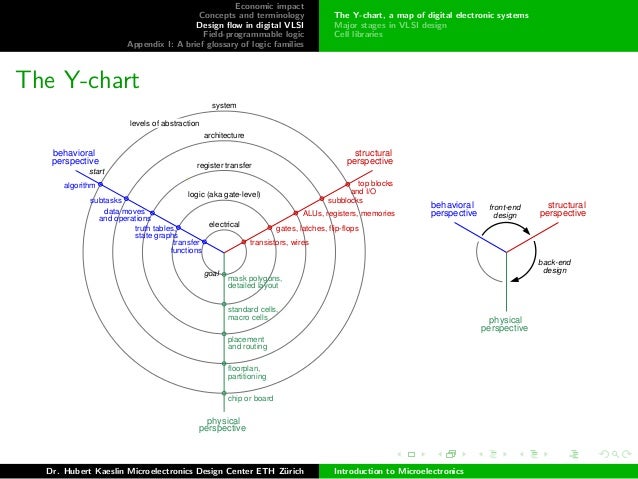
The Y-chart, a vital device in Very-Massive-Scale Integration (VLSI) design, gives a strong visible illustration of timing relationships inside a digital circuit. It is instrumental in understanding and optimizing the timing conduct of advanced built-in circuits, enjoying a essential position in making certain the right and environment friendly operation of the ultimate product. This text delves deep into the Y-chart, exploring its construction, functions, interpretation, and significance within the trendy VLSI design circulation.
Understanding the Fundamentals: Clock Domains and Timing Constraints
Earlier than diving into the intricacies of the Y-chart, it is important to understand the underlying ideas of clock domains and timing constraints. In a VLSI design, completely different elements of the circuit might function at completely different clock frequencies or with asynchronous clock alerts. These distinct operational areas are often called clock domains. Information switch between these domains introduces timing challenges that want cautious consideration.
Timing constraints outline the appropriate timing relationships inside a circuit. These constraints specify the utmost allowable delay (propagation delay) for alerts to journey between completely different elements, in addition to the setup and maintain occasions required for dependable information seize in flip-flops. Violations of those constraints can result in malfunctioning circuits.
The Y-Chart’s Construction and Parts
The Y-chart, also called a timing diagram or a timing evaluation chart, visually depicts the timing relationships between three key factors in a synchronous circuit:
- Launch Clock (CLK_L): The clock edge that initiates the info switch.
- Seize Clock (CLK_C): The clock edge that captures the info on the vacation spot.
- Information (Information): The info sign being transferred.
The chart’s title comes from its resemblance to the letter "Y," with the three elements forming the branches. Every department represents a essential timing parameter:
- Launch Clock to Information (CLK_L to Information): This represents the time it takes for the info to turn into secure after the launch clock edge. This contains the clock-to-Q delay of the supply flip-flop and the combinational logic delay.
- Information to Seize Clock (Information to CLK_C): This represents the time it takes for the info to achieve the vacation spot flip-flop earlier than the seize clock edge. This primarily contains the combinational logic delay between the supply and vacation spot flip-flops.
- Launch Clock to Seize Clock (CLK_L to CLK_C): This represents the time distinction between the launch and seize clock edges. That is essential for figuring out the full time out there for information propagation.
Analyzing Timing Relationships with the Y-Chart
The Y-chart facilitates the evaluation of varied timing parameters:
- Setup Time: The minimal time the info should be secure earlier than the seize clock edge. A violation happens if the Information to CLK_C path is shorter than the required setup time.
- Maintain Time: The minimal time the info should stay secure after the seize clock edge. A violation happens if the Information to CLK_C path is simply too brief, doubtlessly inflicting metastability points.
- Clock Skew: The distinction in arrival time of the launch and seize clocks at their respective flip-flops. Extreme clock skew can scale back the efficient timing finances.
- Propagation Delay: The full time taken for the info to propagate from the supply to the vacation spot. That is the sum of the CLK_L to Information and Information to CLK_C paths.
- Slack: The distinction between the out there time and the required time for information propagation. Optimistic slack signifies that the timing constraint is met, whereas adverse slack signifies a timing violation.
Functions of the Y-Chart in VLSI Design
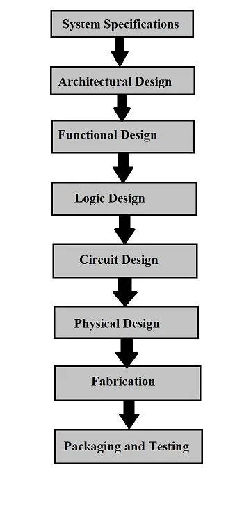
The Y-chart is an indispensable device all through the VLSI design circulation:
- Timing Evaluation: It gives a transparent visualization of timing relationships, enabling engineers to determine potential timing violations early within the design course of. Static Timing Evaluation (STA) instruments usually generate Y-charts or comparable representations to focus on essential paths and problematic areas.
- Clock Area Crossing (CDC) Evaluation: When information is transferred between asynchronous clock domains, the Y-chart is essential in analyzing setup and maintain occasions, making certain dependable information switch and mitigating metastability dangers. Specialised CDC evaluation instruments regularly make use of Y-chart-like representations.
- Optimization and Design Refinement: By figuring out essential paths and timing violations, the Y-chart guides design optimization efforts. Strategies like pipelining, buffering, and clock gating could be strategically utilized to enhance timing efficiency.
- Verification and Validation: The Y-chart helps confirm that the design meets its timing necessities. It facilitates the comparability of simulation outcomes with the anticipated timing conduct.
- Debugging and Troubleshooting: When timing points come up, the Y-chart assists in pinpointing the supply of the issue, whether or not it is extreme propagation delay, inadequate setup time, or clock skew.
Limitations and Alternate options
Whereas the Y-chart provides a strong visualization of timing relationships, it has limitations:
- Complexity: For extremely advanced circuits with quite a few clock domains and complex information paths, the Y-chart can turn into unwieldy and troublesome to interpret.
- Abstraction: The Y-chart usually represents simplified timing fashions, neglecting components like course of variations and temperature results. Extra detailed evaluation may require extra refined instruments.
Alternate options to the Y-chart embody:
- Timing reviews generated by STA instruments: These reviews present detailed numerical information on timing parameters, providing a extra complete evaluation than the visible illustration of the Y-chart.
- Waveform viewers: These instruments enable visualization of sign waveforms over time, offering a extra granular view of timing conduct.
Conclusion: The Y-Chart’s Enduring Relevance in VLSI
Regardless of the supply of extra refined instruments, the Y-chart stays a priceless asset in VLSI design. Its easy but efficient visible illustration of timing relationships gives essential insights into circuit conduct, facilitating environment friendly design, optimization, and verification. Whereas it won’t be the only device for advanced designs, its skill to shortly spotlight potential timing issues and supply a transparent understanding of elementary timing parameters makes it an everlasting and important aspect within the VLSI engineer’s toolkit. Its continued use underscores its worth in understanding the intricate timing dynamics of immediately’s advanced built-in circuits. Mixed with different superior timing evaluation strategies and instruments, the Y-chart ensures the event of dependable, high-performance VLSI techniques.


![[100% OFF] Static Timing Analysis: VLSI with Certificate of Completion](https://www.tutorialbar.com/wp-content/uploads/4911468_cb10_2-749x421-1-788x442.jpg)

Closure
Thus, we hope this text has offered priceless insights into The Y-Chart in VLSI: A Complete Information to Timing Evaluation and Optimization. We hope you discover this text informative and useful. See you in our subsequent article!